Can we enable everyday objects in outdoor environments to communicate with cars and smartphones, without worrying about power? Such a capability could enable transformative visions such as connected cities and smart fabrics that promise to change the way we interact with objects around us. For instance, bus stop posters and street signs could broadcast digital content about local attractions or advertisements directly to a user’s car or smartphone. Posters advertising local artists could broadcast clips of their music or links to purchase tickets for upcoming shows. A street sign could broadcast information about the name of an intersection, or when it is safe to cross a street to improve accessibility for the disabled.
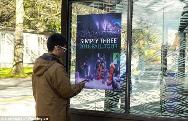
Bus stop posters and street signs could broadcast digital content about local attractions or advertisements directly to a user’s car or smartphone. Image courtesy of University of Washington.
Such ubiquitous low-power connectivity would also enable smart fabric applications—smart clothing with sensors integrated into the fabric itself could monitor a runner’s gait or vital signs and directly transmit the information to their phone.
While recent efforts on backscatter communication dramatically reduce the power requirements for wireless transmissions, they are unsuitable for outdoor environments. Specifically, existing approaches either use custom transmissions from RFID readers or backscatter ambient Wi-Fi and TV transmissions. RFID-based approaches are expensive in outdoor environments given the cost of deploying the reader infrastructure. Likewise, while Wi-Fi backscatter is useful indoors, it is unsuitable for outdoor environments. Finally, TV signals are available outdoors, but smartphones as well as most cars do not have TV receivers and hence cannot decode the backscattered signals.
Taking a step back, the requirements for our target applications are four-fold: 1) The ambient signals we hope to backscatter must be ubiquitous in outdoor environments, 2) devices such as smartphones and cars must have the receiver hardware to decode our target ambient signals, 3) it should be legal to backscatter in the desired frequencies without a license, which precludes cellular transmissions, and 4) in order to retrieve the backscattered data, we should ideally have a software-defined radio like capability to process the raw incoming signal without any additional hardware.
FM Fits the Bill
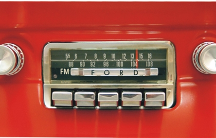
Our key contribution is the observation that FM radio satisfies the above constraints. Broadcast FM radio infrastructure already exists in cities around the world. These FM radio towers transmit at a high power of several hundred kilowatts which provides an ambient signal source that can be used for backscatter communication. Additionally, FM radio receivers are included in the LTE and Wi-Fi chipsets of almost every smartphone and have recently been activated on Android devices in the United States. Further, the FCC provides an exemption for low-power transmitters to operate on FM bands without requiring a license. Finally, unlike commercial Wi-Fi, Bluetooth and cellular chipsets that provide only packet level access, FM radios provide access to the raw audio decoded by the receiver. These raw audio signals can be used in lieu of a software-defined radio to extract the backscattered data.
Building on this, we transform everyday objects into FM radio stations. Specifically, we design the first system that uses FM signals as an RF source for backscatter. We show that the resulting transmissions can be decoded on any FM receiver including those in cars and smartphones. Achieving this is challenging for two key reasons:
- Unlike software radios that give raw RF samples, FM receivers output only the demodulated This complicates decoding since the backscatter operation is performed on the RF signals corresponding to the FM transmissions while an FM receiver outputs only the demodulated audio. Thus, the backscatter operation has to be designed to be compatible with the FM demodulator.
- FM stations broadcast audio that ranges from news channels with predominantly human speech, to music channels with a richer set of audio In addition, they can broadcast either a single stream (mono mode) or two different audio streams (stereo mode) to play on the left and right speakers. Ideally, the backscatter modulation should operate efficiently with all these FM modes and audio characteristics.
To address these challenges, we leverage the structure of FM radio signals. At a high level, we introduce a modulation technique that transforms backscatter, which is a multiplication operation on RF signals, into an addition operation on the audio signal output by FM receivers. This allows us to embed audio and data information in the underlying FM audio signals. Specifically, we use backscatter to synthesize baseband transmissions that imitate the structure of FM signals, which makes it compatible with the FM demodulator. Building on this, we demonstrate three key capabilities:
- Overlay backscatter. We overlay arbitrary audio on ambient FM signals to create a composite audio signal that can be heard using any FM receiver, without any additional We also design a modulation technique that overlays digital data which can be decoded on FM receivers with processing capabilities, e.g., smartphones.
- Stereo backscatter. A number of FM stations, while operating in the stereo mode, do not effectively utilize the stereo We backscatter data and audio on these underutilized stereo streams to achieve a low interference communication link. Taking it a step further, we can also trick FM receivers to decode mono FM signals in the stereo mode, by inserting the pilot signal that indicates a stereo transmission. This allows us to backscatter information in the interference-free stereo stream.
- Cooperative backscatter. Finally, we show that using cooperation between two smartphones from users in the vicinity of the backscattering objects, we can imitate a MIMO system that cancels out the audio in the underlying ambient FM This allows us to decode the backscatter transmissions without any interference.
To evaluate our design, we first perform a survey of the FM signal strengths in a major metropolitan city and identify unused spectrum in the FM band, which we then use in our backscatter system. We implemented a prototype FM backscatter device using off-the-shelf components and used it to backscatter data and arbitrary audio directly to a Moto G1 smartphone and 2010 Honda CRV’s FM receiver. We compared the trade-offs for the three backscatter techniques described above and achieve data rates of up to 3.2 kbps and ranges of 5–60 ft. Finally, we designed and simulated an integrated circuit that backscatters audio signals, showing that, if fabricated, consumes only 11.07 µW.
Survey of FM Radio Signals
Public and commercial FM radio broadcasts are a standard in urban centers around the world and provide a source of ambient RF signals in these environments. In order to cover a wide area and allow for operation despite complex multipath from structures and terrains, FM radio stations broadcast relatively high power signals. In the United States, FM radio stations produce an effective radiated power of up to 100 kW.
We surveyed the signal strength of FM radio transmissions across Seattle, WA. We drove through the city and measured the power of ambient FM radio signals using a software defined radio (SDR, USRP E310) connected to a quarter-wavelength monopole antenna (Diamond SRH789). Since there are multiple FM radio stations in most US cities, we recorded signals across the full 88–108 MHz FM spectrum and identified the FM station with the maximum power at each measurement location. We calibrated the raw SDR values to obtain power measurements in dBm using reference power measurements performed with a spectrum analyzer (Tektronix MDO4054B-3). We divided the surveyed area into 0.8 mi× 0.8 mi grid squares and determine the median power in each for a total of 69 measurements.
Structure of FM Radio Transmissions
We leverage the structure of FM signals to embed audio and data. In this section, we outline the background about FM radio necessary to understand our design.
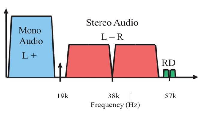
Figure 1. Structure of FM Radio Transmissions. Baseband audio signals transmitted in stereo FM broadcasts.
Audio Baseband Encoding. Fig. 1 illustrates the base-band audio signal transmitted from a typical FM station. The primary component is a mono audio stream, which is an amplitude modulated audio signal between 30 Hz and 15 kHz. With the advent of stereo speakers with separate left and right audio channels, FM stations incorporated a stereo stream transmitted in the 23 to 53 kHz range. To maintain backward compatibility, the mono audio stream encodes the sum of the left and right audio channels (L+R) and the stereo stream encodes their difference (L-R). Mono receivers only decode the mono stream, while stereo receivers process the mono and stereo streams to separate the left (L) and right (R) audio channels. The FM transmitter uses a 19 kHz pilot tone to convey the presence of a stereo stream. Specifically, in the absence of the pilot signal, a stereo receiver would decode the incoming transmission in the mono mode and uses the stereo mode only in the presence of the pilot signal. In addition to the mono and stereo audio streams, the transmitter can also encode the radio broadcast data sys- tem (RDS) messages that include program information, time and other data sent at between 56 and 58 kHz.
RF Encoding. As the name suggests, FM radio uses changes in frequency to encode data. Unlike packet based radio systems such as Bluetooth and Wi-Fi, analog FM radio transmissions are continuous in nature. An FM radio station can operate on one of the 100 FM channels between 88.1 to 108.1 MHz, each separated by 200 kHz. Specifically, FM radio signals are broadcast at the carrier frequency fc in one of these FM bands, and information at each time instant is encoded by a deviation from fc.
Backscattering FM Radio
Backscattering FM radio transmissions and decoding them on mobile devices is challenging because FM receivers only output the decoded audio, while the backscatter operation is performed on the RF signals. To address this, we show that by exploiting the FM signal structure, we can transform backscatter, which performs a multiplication operation in the RF domain, into an addition operation in the audio domain.
FM Backscatter capabilities
In addition to overlay backscatter where the backscattered audio data is simply overlaid on top of the ambient FM signals, there are two additional backscatter techniques: stereo backscatter and cooperative backscatter.
Stereo Backscatter. We consider two scenarios: 1) A mono radio station that does not transmit a stereo stream, and 2) A stereo station that broadcast news information.
- Mono to stereo While many commercial FM radio stations broadcast stereo audio, some stations only broadcast a mono audio stream. In this case, all the frequencies corresponding to the stereo stream (15- 58 kHz in Fig. 1) are unoccupied. Thus, they can be used to backscatter audio or data without interference from the audio signals in the ambient FM transmissions. Utilizing these frequencies however presents two technical challenges. First, the FM receiver must be in the stereo mode to decode the stereo stream, and second FM receivers do not provide the stereo stream but instead only output the left and right audio channels (L and R).
To address the first challenge, we note that FM uses the 19 kHz pilot signal shown in Fig. 1 to indicate the presence of a stereo stream. Thus, in addition to backscattering data, we also backscatter a 19 kHz pilot signal.
To address the second challenge, we note that FM receivers do not output the stereo stream (L-R) but instead output the left and right audio streams. To recover our stereo backscatter signal, all we have to do is compute the difference between these left (L) and right (R) audio streams. This allows us to send data/audio in the unoccupied stereo stream of a mono FM transmission.
- Stereo backscatter on news While many FM stations transmit in the stereo mode, i.e., with the 19 kHz pilot tone in Fig. 1, in the case of news and talk radio stations, the energy in the stereo stream is often low. This is because the same human speech signal is played on both the left and right speakers. We verified this empirically by measuring the stereo signal from four different radio stations. We captured the audio signals from these stations for a duration of 24 hours and computed the average power in the stereo stream and compared it with the average power in 16-18 kHz, which are the empty frequencies in Fig. 1.
The signal plots confirmed that in the case of news and talk radio stations, the stereo channel has very low energy. Based on this observation, we can backscatter data/audio in the stereo stream with significantly less interference from the underlying FM signals. However, since the underlying stereo FM signals already have the 19 kHz pilot signal, we do not backscatter the pilot tone.
Cooperative backscatter. Consider a scenario where two users are in the vicinity of a backscattering object, e.g., an advertisement at a bus stop. The phones can share the received FM audio signals through either Wi-Fi direct or Bluetooth and create a MIMO system that can be used to cancel the ambient FM signal and decode the backscattered signal. Specifically, we set the phones to two different FM bands: the original band of the ambient FM signals ( fc) and the FM band of the backscattered signals ( fc + fback ).
Data Encoding with Backscatter
We encode data using the audio frequencies we can transmit using backscatter. The key challenge is to achieve high data rates without a complex modulation scheme to achieve a low power design. High data rate techniques like OFDM have high computational complexity (performing FFTs) as well as have high peak-to-average ratio, which either clips the high amplitude samples, or scales down the signal and as a result limits the communication ranges. Instead we use a form of FSK modulation in combination with a computationally simple frequency division multiplexing algorithm.
Data Encoding Process. At a high level the overall data rate of our system depends on both the symbol rate and the number of bits encoded per symbol. We modify these two parameters to achieve three different data rates. We present a low rate scheme for low SNR scenarios as well as a higher rate scheme for scenarios with good SNR.
100 bps. We use a simple binary frequency shift keying scheme (2-FSK) where the zero and one bits are represented by the two frequencies, 8 and 12 kHz. Note that both these frequencies are above most human speech frequencies to reduce interference in the case of news and talk radio programs. We use a symbol rate of 100 symbols per second, giving us a bit rate of 100 bps using 2-FSK. We implement a non-coherent FSK receiver which compares the received power on the two frequencies and output the frequency that has the higher power. This eliminates the need for phase and amplitude estimation and makes the design resilient to channel changes.
1.6 kbps and 3.2 kbps. To achieve high bit rates, we use a combination of 4-FSK and frequency division multiplexing. Specifically, we use sixteen frequencies between 800 Hz and 12.8 kHz and group them into four consecutive sets. Within each of these sets, we use 4-FSK to transmit two bits. Given that there are a total of four sets, we transmit eight bits per symbol. We note that, within each symbol, there are only four frequencies transmitted amongst the designated 16 to reduce the transmitter complexity. We choose symbol rates of 200 and 400 symbols per second allowing us to achieve data rates of 1.6 and 3.2 kbps. We note that our experiments showed that the BER performance degrades significantly when the symbol rates are above 400 symbols per second. Given this limitation, 3.2 kbps is the maximum data rate we achieve which is sufficient for our applications.
Maximal-ratio combining. We consider the original audio from the ambient FM signal to be noise, which we assume is not correlated over time; therefore we can use maximal-ratio combining (MRC) to reduce the bit-error rates. Specifically, we backscatter our data N times and record the raw signals for each transmission. Our receiver then uses the sum of these raw signals in order to decode the data. Because the noise (i.e., the original audio signal) of each transmission are not correlated, the SNR of the sum is therefore up to N times that of a single transmission.
Implementation
We built a hardware prototype with off-the shelf components, which we used in all our experiments and to build proof of concept prototypes for our applications. We then designed an integrated circuit-based FM backscatter system and simulated its power consumption.
Off-the-shelf design. We use the NI myDAQ as our base-band processor, which outputs an analog audio signal from a file. For our FM modulator, we use the Tektronix 3252 arbitrary waveform generator (AWG) which has a built-in FM modulation function. The AWG can easily operate up to 10s of MHz and can generate an FM modulated square wave as a function of an input signal. Interfacing the NI myDAQ with the AWG gives us the flexibility of using the same setup to evaluate audio and data modulation for both mono and stereo scenarios. We connect the output of the AWG to our RF front end, which consists of the ADG902 RF switch. We design the switch to toggle the antenna between an open and short impedance state.
IC Design. In order to realize smart fabric and posters with FM backscatter, we translate our design into an integrated circuit to minimize both size and cost, and scale to large numbers. We implemented the FM backscatter design in the TSMC 65 nm LP CMOS process. A detailed description of the IC architecture is presented below.
Baseband processor. The baseband data/audio is generated in the digital domain using a digital state machine. We wrote Verilog code for the baseband and translated it into a transistor-level implementation using the Synopsis Design Compile tool. Our implementation of a system transmitting mono audio consumes 1 µW.
FM modulator. The FM modulator is based on an inductor and capacitor (LC) tank oscillator with an NMOS and PMOS cross-coupled transistor topology. We leverage the fact that the capacitors can be easily switched in and out and design a digitally controlled oscillator to modulate the oscillator frequency. We connect a bank of 8 binary weighted capacitors in parallel to an off-chip 1.8 mH inductor and control the digital capacitor bank from the output of the baseband processor to generate a FM modulated output. We simulate the circuit using Cadence Spectre. Our 600 kHz oscillator with a frequency deviation of 75 kHz consumes 9.94 µW.
Backscatter switch. We implement the backscatter switch using an NMOS transistor connected between the antenna and ground terminals. The square wave output of the FM modulator drives the NMOS switch ON and OFF, which toggles the antenna between open and short impedance states to backscatter FM modulated signals. We simulate the switch in Cadence to show it consumes 0.13 µW of power while operating at 600 kHz. Thus, the total power consumption of our FM backscatter system is 11.07 µW.
Audio Performance
Beyond data, our design also enables us to send arbitrary audio signals using FM backscatter. In this section, we evaluate the performance of FM audio backscatter. As before we set the FM transmitter to send four, 8 s samples of sound recorded from local radio stations. To evaluate the quality of the resulting audio signals, we use perceptual evaluation of speech quality (PESQ) which is a common metric used to measure the quality of audio in telephony systems PESQ outputs a perception score between 0 and 5, where 5 is excellent quality. We evaluate this metric with overlay, stereo, and collaborative backscatter.
Audio with overlay backscatter. In the case of overlay backscatter, we have two different audio signals: one from the backscatter device and the second from the underlying FM signals. We compute the PESQ metric for the backscattered audio information and regard the background FM signal as noise. We repeat the same experiments as before where we change the distance between the backscatter device and the Moto G1 smartphone at different power levels of FM signals. We repeat the experiments ten times for each parameter configuration and plot the results. The resulting plot shows that the PESQ is consistently close to 2 for all power numbers between -20 and -40 dBm at distance of up to 20 feet. We see similar performance at -50 dBm up to 12 feet. Unlike data, audio backscatter requires a higher power of -50 dBm to operate since one can perform modulation and coding to decode bits at a lower data rate at down to -60 dBm. We also note that in traditional audio, a PESQ score of 2 is considered fair to good in the presence of white noise; however our interference is real audio from ambient FM signals. What we hear is a composite signal, in which a listener can easily hear the backscattered audio at a PESQ value of two. We attach samples of overlay backscatter audio signals with PESQ values of 2.5, 2, 1.5 and 1 respectively in the following video for demonstration:
https://smartcities.cs.washington.edu/pesq.mp4
Using FM Receivers in Cars
We evaluate our backscatter system with an FM radio receiver built into a car in order to further demonstrate the potential for these techniques to enable connected city applications. The FM receivers built into cars have two distinct differences compared to smartphones. First, car antennas can be better optimized compared to phones as they have less space constraints, the body of the car can provide a large ground plane, and the placement and orientation of the antenna can be precisely defined and fixed unlike the loose wires used for headphone antennas. Because of this, we expect the RF performance of the car’s antenna and radio receiver to be significantly better than the average smartphone. Second, although recent car models have begun to offer software such as Android Auto or Apple CarPlay, the vast majority of car stereos are still not programmable and therefore limited to using our overlay backscatter technique.
To test the performance of the car receiver with our backscatter system, we used an experimental setup similar to the one described in the full text paper (Section 5) for the smartphone. Specifically, we place the backscatter antenna 12 ft away from the transmitting antenna which we configure to output a measured power, and evaluate the quality of the audio signal received in a 2010 Honda CRV versus range. Because the radio built into the car does not provide a direct audio output, we use a microphone to record the sound played by the car’s speakers. To simulate a realistic use case we perform all experiments with the car’s engines running and the windows closed. We backscatter the same signals used above to measure SNR and PESQ. The audio quality versus range for two different power values demonstrated that our system works well up to 60 ft.
For more details, see the full text paper, FM Backscatter: Enabling Connected Cities and Smart Fabrics.
